March 31, 2019

Building A Clone Of The Vico Vibe Tremolo

The jordan vico vibe interested me in early 2012 mainly because it's so simple. As a rookie solder jockey that wanted to build every type of pedal to try them all the specs sounded very appealing. The tremolo circuit is about as complicated as a fuzz face (the pedal I built before that) and didn't use any optocouplers .

Of course it's a little more complicated than that. The vico vibe is reported to have a volume drop when engaged and the circuit is kind of unusual. It doesn't have any buffers, just two resistors and an LFO that periodically dumps all signal to ground to create the tremolo effect.

This is the classic schematic as found online:

IvIark made a vero layout for this:

I assumed the volume drop needed to be counteracted with a boost circuit, so I built an SHO mosfet boost and connected it right after the circuit. The volume would be set with a trim pot and another trim pot was used to bias the vico vibe circuit.

The final schematic looked like this

I connected these two circuits in series in one box and after careful calibration by ear they sound great. This is vital, though, as the DEPTH and TRIM control interact and trim set too much to either direction will affect the minimun depth, which will make the tremolo disappear.

Here's a picture of the two vico vibes I built:

One is the two vero circuits in one enclosure with two rate controls (red and blue knob) that can be switched with the left footswitch. The other one is both circuits built on one pcb and fits in a 1590A.

I shared the pcb and it can be ordered here (note I don't make money on shared projects).

March 7, 2019

Building A Runoffgroove Modified EA Tremolo

For a while now, I wanted to build a nice, good sounding tremolo effect. I built the vico vibe in the past but it's quite finicky to bias and has a volume drop when engaged, but compensating this with a simply SHO-style boost after it led to weird interactions. Once it's biased it sounds great, and works well with fuzz and overdrive in front of it. It's actually one of my favorite effects.

But in this case I was looking for something that would be more versatile and would simply work and be reliable. I read a few blogs and recommendations and one website that always intrigued me was Runoffgroove and their original circuits as well as their archive website homewrecker detailing clones and mods. This is where I found the "modified EA Tremolo", which is based on a circuit found on General Guitar Gadgets, which in turn was inspired by a tremolo circuit originally published in 1968 in the Electronic Australia Magazine. Phew.

I chose the ROG version because it is simpler and has a lower parts count. This is the schematic:


My requirements for this project were that I wanted to make a layout that has board-mounted pots, is reasonably small, allows for the pulsing LED to be used both as an on/off and rate indicator (to only have one LED for both), and I wanted it to fit Tayda's new predrilled enclosures. I'm tired of drilling them by hand and sometimes it's nice to use a painted predrilled enclosure and whip something up in an hour.

I made a layout in Eagle and got it fabricated at oshpark (here is a link to order my shared layout). During assembly and firing it up for the first time I though I had made a mistake because there was no sound when the effect was engaged. I also had weird voltages. However the trim pot needs to be adjusted until there are 4.5-5v at Q1 drain. This voltage does not come gradually, it's suddenly there at one point in the rotation and the range is really small, so be careful to get this right, otherwise there is no effect. I subsituted the BS170 for a 2N7000 (opposite pinout), the J201 for a 2N5457 and the 2N5088 for a BC547 (I think), as I had these on hand.

It came out great and sounds pretty good. More "gentlemanly" and subtle than the vico vibe, which I will present in another post (it's a longer story). Maybe I will add a sticker or paint something on it, or maybe I'll keep the bare black/aluminum look.


March 2, 2019

Building A Clone Of The Way Huge Aqua Puss mk1 MN3005

In 2009 the original Way Huge Aqua Puss mk1 was reversed on freestompboxes.org and revealed to be a slight variation of the Boss DM-2 with Panasonic MN3005 Delay Chip. 


There was a community project and a PCB made up and luckily I managed to get one of the last ones in 2012. It spent some time in a box until I finally got around to finishing it a few years ago. Unfortunately, many of the original links and pictures were dead by the time I got around to working on it so I had to kind of scrape the few tidbits and a BOM together to finish the pedal. The early Aquaboy project on madbeanpedals.com, which was at first focussed on the Way Huge version rather than the original DM-2 was a great help. It featured the schematic and a partslist that could be related to the original schematic.

I managed to finish the pedal, put it in a tall 1590BB and even calibrate it with the DM-2 instructions. This is how it originally looked. I built it exclusively with Dale CMF55 resistors and wima and panasonic caps. I order to make it as high quality as possible, I also drilled holes for the little tabs to keep the potentiometers from turning. Usually everyone just clips those tabs off, but they have a reason. Unfortunately that meant the holes could be seen next to the knobs, which isn't such a pretty look.


I decided to add a control plate to hide the extra holes for the pots and to tell me which knob is controlling which function. This is made from PCB material without copper tracks and was designed in Eagle. It looks really good now in my opinion.


As the PCB I acquired was the last of the FSB community PCBs, and I started getting the hang of Eagle, I then decided to make my own PCB and maybe try a few mods and sell a few pedals if there is more interest. It took a few days, but I made a PCB layout that was inspired by the original Aqua Puss, but a bit smaller, giving me more room to work with in the box and maybe allow mods like double time and modulation. I got them fabricated and they came out awesome and work beautifully and for some reason are quieter than the FSB version. 

I have a few left for sale on my site including a download with partslist and schematic for anyone who wants to try to build their own.


This is the second Aqua Puss Mk1 I built, the first with my own PCB.


(this one actually has the first version of my PCB, which required two jumpers to work because I forgot the connections on the schematic. V2 shown above now has more generous distances between the components and works right away). 

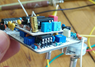
My third version was built with some tantalum capacitors instead of the electrolytic caps near the BBD to allow for a double delay board daughter board that plugs into the original BBD socket. I traced sabrotones dual delay board and made my own PCB that I got fabricated. It works as expected and calibration is not as difficult as I thought. One simply has to calibrate with one BBD as usual and then plug the BBD into the first slot on the double delay board and calibrate the second BBD with the remaining trimmers the same way. 


This is the finished product. I decided to rename it the Acqua Vitae to avoid issues with copyright and underline it's not a straight "replica" like the FSB board, but rather a reinvention inspired by the original APmk1. It sounds noticeably warmer/darker with two BBDs but the delay time more than doubled (I'm guessing due to the additional darkness clock noise is filtered slightly better and the BBDs can be adjusted for longer delay times). I guess the tantalums in the signal path also darken the signal slightly.


I'm currently working on a version with modulation and a few more quirks that I will talk about in another post.